| |
2002up Superduty Ford F250/350 Proper Foglight Operation
and SUVLIGHTS Harness Fix
Note:
I provide these mods at my own expense - not only in the research, but also the generation of the web pages and the hosting fees that I pay monthly, along with all the phone help I've provided over the years. I was wondering if you like these mods and they are useful to you ... would you mind kicking in a few bucks as a way of saying "Thanks" and helping to offset my costs? Seriously, a few dollars. Buy me a beer. Nothing mandatory here. By all means enjoy my mods, and feel free to call me anytime with questions or ideas.
The dreaded "PayPal" link is below. If you don't have or use PayPal, don't sweat it. Grab the six pack, the screwdriver, the soldering iron, and have fun. Send me a success email when it works. Best Wishes -steve
This all started when I ordered the upgraded headlight harness from suvlights.com. On the 2002 truck, installation of this harness can lead to erratic behavior with regard to the interaction between the foglamps and the high beam headlights. Often the high beams will not turn off, or there is substantial delay when using the flash-to-pass (pulling the lefthand stalk back) making this function almost useless. This problem has been posted several times on thedieselstop.com, by myself and others.
It all stems from Ford's idea that high beams and foglamps should never be on at the same time. Ford accomplishes this by using the instrument cluster high beam indicator as the ground path for the coil of the K26 foglamp relay. If the high beams are switched on, the instrument cluster light is on, the ground path of the foglamp relay coil is now at +12 volts, and the foglamp relay opens. Yea team. To make matters worse, early versions of the wiring diagrams did not depict this wiring accurately. To make matters evenest more worserest, the K26 relay is buried deep within the Central Junction Box (aka CJB, the fusebox under the dash) so that it is not a "user-serviceable" part.
This modification will show how to kill one or both birds with one stone. The suvlights harness will function correctly under all conditions (if you have one), and your foglamps will be ON when you decide they should be on, and OFF when you turn them off (stock trucks too). It's that simple. This is a "factory" quality modification, and doesn't involve a bunch of relays, new wiring, crawling under the truck, or trips to Radio Shack. It doesn't stress or overheat any circuits, and doesn't tax the performance of any components beyond design intent. Plus, as far as I know, it's perfectly legal. Note that your state may not allow operation of fog lights and high beams at the same time. I dunno.
I really check and test everything I do. However, do this modification at your own peril. I cannot be responsible for your warranty, mojo, hair loss, law enforcement woes, mortgage rate, Viagra supply, or anything else that might and/or might not befall you. For USA 2002-2005 MODELS ONLY, as far as I know. Canadian/DRL equipped models are different. This information is gladly provided for educational purposes only. Your mileage may vary. Yadda yadda yadda...
Please read ALL of the directions before starting!
- - - - -There are some shortcuts you may wish to take - - - - -
Tools and Stuff Needed:
- 10mm nut driver or socket
- 8mm nut driver or socket
- very small flat blade screwdrivers or seal picks
- 18-24 inches of light gauge wire (18-22ga. or so)
- crimp ring terminal with 1/4" hole
- terminal crimp pliers
- soldering iron, solder
- small shrink wrap tube
Difficulty Rating:  2 beers 2 beers
Ratings 1-5, Sixpack, Case, BREWERY
PLEASE READ THE FOLLOWING:
MODELS THAT IT DOES WORK ON
** 12/01 and Later builds of 2002 Model Year
** 2003 Model Year with 7.3 liter Powerstroke (aka the "Jace Variant")
** 2003 Model Year with 6.0 liter Powerstroke (aka the "BisonFarmer Variant")
** 2004 Model Year (F-250?) (aka the "Specularius Variant")
** 2005 Model Year (so far)
MODELS THAT IT DOES *NOT* WORK ON
** SOME 11/01 and Earlier builds of 2002 Model Year
** 2001, 2000, 1999, etc Model Year
** Candian Vehicles / Vehicles with "DRL" Daytime Running Lights
** Non-Superduties, e.g. F-150
ANY vehicle with BLACK wire instead of Light Green with Black Tracer at Pin 13 of C270a. This is a good check, if you aren't sure about the build or DRL status of your truck. Pull the fusebox, check the wire color, and if it's a black wire STOP. The mod won't work. If I ever get my hands on a Canadian truck, I'll try to figure it out. Bring Molsen!
Here is the latest wiring diagram, from the November 2002 edition of the Ford Service DVD. Many thanks to Val Bluestein (valbluste), who's unsolicited help in getting the correct wiring diagram made all this possible, and was the major stimulus for me to put this page together. Notice the diode, which effectively keeps foglamps from triggering high beams. Unfortunately, the reverse is not true, and when there is insufficient drain load to let the relay coil feed to collapse (like when you install an suvlights harness), the circuit makes the high beams stay on more than they should. This was a crappy Ford factory wiring idea to begin with. Maybe it's for legal reasons. Who knows what evil lurks in the .... nevermind.
STEP 1
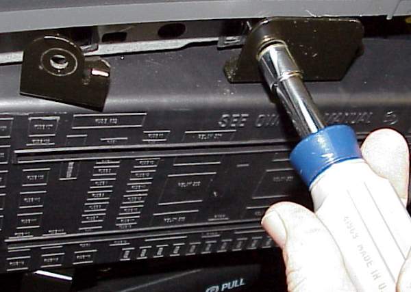
Pop off the fusebox cover under the steering wheel. The CJB is held to the dash with 4 bolts - use a 10mm nutdriver or socket to loosen them. They tend to be tight.
STEP 2 (Note - Quick and Dirty - Jump to STEP 5)
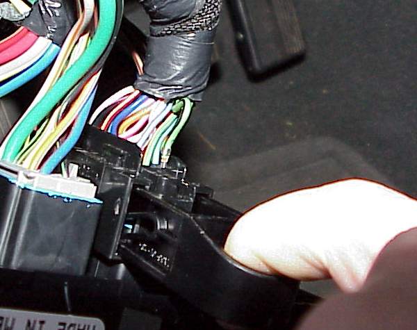
Release connector C270a, which is on the RH side of the back of the CJB. It's the only one with a horseshoe handle, which you pull out from the connector to release the connector from the CJB.
STEP 3
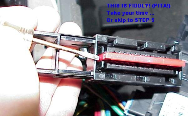
Using a few small flat-blade screwdrivers in the slots at the ends, carefully pry out the red terminal retention bar from the connector. The red plastic bar should be fully removed from the connector. You may need to pry back the locking tabs slightly from the back side of the connector (not shown).
STEP 4
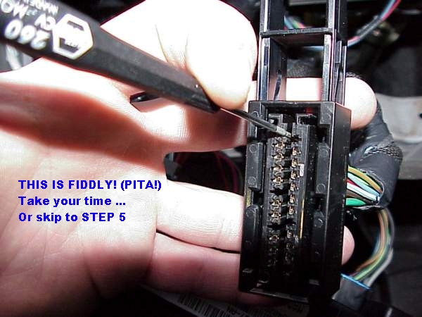
The terminal is released from the connector with a very small screwdriver. place the screwdriver in the slot beside the terminal you want to remove, and lever the little metal tab on the terminal in. At the same time, pull on the wire on the backside of the connector. It will slide right out when the metal tab is pressed in fully. This is a bit fiddly; be patient. Get a flashlight and check it out in the middle of the connector. Once you see what you are trying to do it will be easy. You are trying to remove pin 13, which is the light green with black tracer wire in the corner. If your wire is not this color, solid black for instance, you may have a Canadian and/or DRL build truck. This modification probably will not work. I'm trying to figure out something for you guys way up North, but so far, the Ford Service information is really poor on these trucks.
STEP 5
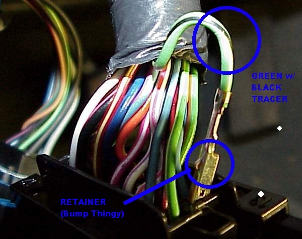
Here you can see the pin 13 wire, the wire color, and the little bump on the terminal that keeps it locked in place. Note that you don't really have to do ANY of the connector dissasembly:
(Quick and Dirty Method)
The idea is to provide a ground wire to the coil of the foglamp relay. You may wish to simply cut the light green/black wire, tie back the harness portion, and solder a ground wire to the remaining bit of wire at PIN 13 of the CONNECTOR. You ground PIN 13 at the CONNECTOR, and NOT the harness wire. Just tape up the cut wire into the harness. You can just splice into the stub connector end of the cut wire, if you want. This will work just as well, and is a whole bunch easier than taking apart the connector, but I wanted to do this mod just right (Slow and Clean Method), and as some of you already know I'm one of THOSE people...
REMEMBER! Ground the short little wire stub at the CONNECTOR, NOT the wire in the harness that goes back into the truck under the dash somewhere. Do this the wrong way and you'll be blowing a headlight fuse everytime until you change it. No damage done, just a new fuse.
STEP 6
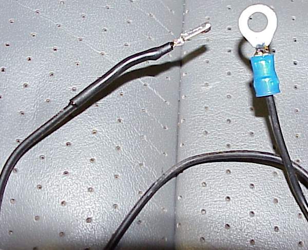
I created a ground wire by soldering 18" of thin, light gauge (18 or 20 ga) automotive wire to the removed pin 13 terminal. The crimp was gently pried apart and the new wire soldered to it. (HINT: If you use the Quick and Dirty Method, the wire size isn't important.) The other end gets a crimped and soldered ring terminal, with about a 1/4" ring size. I also shrinked-wraped some insulation over the soldered terminal to neaten things up, but this really isn't necessary, and if you make this assembly too thick, it won't fit back into the C270a connector. (Remember, THIN wire. You're only grounding a relay; maybe 200mA max.) Did I mention I was one of THOSE people ?!?
Plug the new ground into the connector, and snap the red connector cross-bar thingy from STEP 3 back into the center slot. Reinstall the connector onto the back of the CJB by pressing inward and closing the horseshoe loop at the same time. Start by making sure the horseshoe is fully extended. The connector will click nicely when seated.
HINT: Don't use your leather seat as a workbench to solder up your wires...
STEP 7
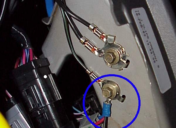
Really convenient grounds exist just to the right of the CJB, bolted into the dash structure braces. You'll need a 8mm nutdriver or socket to get these off. They are tight from the factory. You can see my nifty new ground wire on the lower bolt in the photo.
Just loosen one of these bolts and slip the ring terminal in there with the rest of the existing wires.
Now's a good time to test, unless you're like me and never make a mistake. Remember that the Foglights are sourced with KEY ON, but the HEADLIGHTS will come on with KEY OFF. You'll have to turn to ignition (but not necessary to start the truck) to check the foglights!
Success?? I knew you'd get it. Bolt the CJB back into place. Make sure the brackets are swiveled in the right direction. Tighten back up, reinstall that cheesy plastic cover (Sequence on the quarter-turn plastic slot fastners is fiddly - try and get them all started before you tighten any of them. It doesn't help that they have springs on them...)
(STEP 8)
Drink celebration beer(s) !
FINISHED !
Here's the updated wiring diagram, so you can see what all this is really about. The point is to provide a ground path for the coil of K26 foglamp relay, other than the high beam indicator lamp. The stock foglamp switch works like it should. High beams can be off or on. No matter. You may find other less tedious ways to do this, the easiest is probably to cut the green/black wire at pin 13 of C270a, leaving 2 inches at the connector to solder to and ground under a screw. The original wire just gets taped into the harness. Remember, the idea is to provide a NEW ground path for the coil of the fog lamp relay - which is at Pin 13 of Connector 270a (the horseshoe handle one). No need to worry about the green/black wire. Just tape it up. This modification will not interfere with the normal operation of the high beam indicator in any way. Everything will work as it SHOULD, with the foglamp switch turning the foglamps ON when you want and OFF when you want.
HERE'S VIDEO PROOF (380Kb) - Post mod demo of foglamps remaining ON while my darling wife flips back and forth between low and high beams. This video is certainly not adult, certianly not very good, and apologies to Procol Harum...
Hope that helps. This is a 20 minute, "two beer" kind of job. Pretty rewarding if you're not real comfortable with this kind of mod, but want to get your hands dirty.
Take back control of your Fogs! Best wishes, S.A. McChesney aka "SteveRacer"
12/15/02, 1/3/03, 2/19/03, 1/27/04, 5/1/05, 1/9/06 (C) 2002-6 S&S Diversified
Feel free to Link, Not to Copy!
|