 Concept to Delivery: S&S is your "one-stop" vendor. |
 CAD Technical CAD Drawing and 3D Modeling with Multi-color Pen Plotting. |
 Turn, Mill, Drill, Cut, Weld, Paint, Create. S&S fabricates your Prototype. |
 SCCA Race Car, Motorsport Preperation, Tuning. |
 S&S can put your business on the web |
||
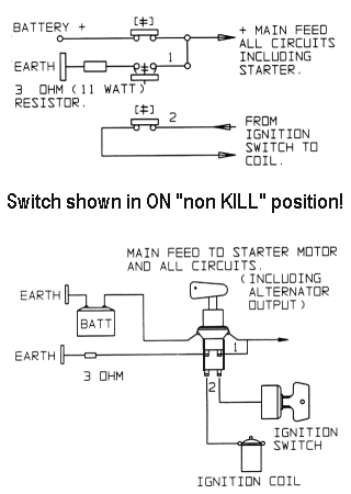
Master "Kill" Switch Wiring for SCCA Race Cars with Alternators This all started back in 1998 or so when my BMW 2002 was still running Improved Touring, and suddenly the then "Denver" powers-that-be mandated all cars shalt haveth a kill switch. Well, fine and dandy. I had a few of the simple BIG RED SWITCH things laying around, but I remember the expensive and horrible results when I tried to install one of these on my '85 MR2 [footnote: The "Lizzy B" ex. T. Lynch and ex. J. DeLuca racing MR2!] . . . anyway, I let the smoke out of some important innner alternator osilfrometer thingies, which was discovered at the racetrack with a dying battery, weak fuel injection, and poor ignition. And Toyota alternator internal domilflachys are NOT cheap. SO... Along comes Bill Hughes, famed NNJR region Tech Inspector Scrutineering Person, and thus is born an article that guides us poor alternator-saddled folks with wiring the special kill switch needed for SCCA racing. Be cause as we all know, REAL race cars don't need no stinkin' alternators. [cough...] Note that my original "MR2" method WILL work, if you isolate the D+ heavy alternator wire, but the only problem is it will likely ruin your alternator if you ever use it. But it WILL kill every circuit on the car, and it does meet the GCR. The GCR is simply concerned with shutting down your car instantly, they really don't care if you ruin your alternator. But for us shoestring guys, even though everything only costs $50 . . . I'd like to keep my alternator healthy. Plus, I've noticed that ONE BIG RED SWITCH is really nice to shut off and make CERTAIN that nothing is left on - no pumps, lights, radios, cigar lighters, neon underbody accents, blue LED winshield washer spray nozzles, subwoofer amps, DVD navigation systems, etc etc etc . . . you know, those race car things that get left on over the winter and make you rush out buy a new battery the early Spring night before a race! I really check and test everything I do. However, do this modification at your own peril. I cannot be responsible for your warranty, mojo, hair loss, law enforcement woes, mortgage rate, Viagra supply, or anything else that might and/or might not befall you. For off-road non-CARB vehicles, as far as I know. Canadian and French vehicles are probably different, if anyone cared. This information is gladly provided for educational purposes only. Your mileage may vary. Yadda yadda yadda... TECHNOTES -- ARTICLE 01:
Now for IT drivers, a master switch is required this year. This switch must kill all power except for an electrically operated fire system, if so equipped. This switch must also shut the motor off, which means that you will need a 3 pole switch, not a single pole. If a single pole is used, two things will happen: 1) The car will keep running because of residual magnetism in the alternator, which will keep the alternator supplying power, and 2) the field being disconnected on the alternator will cause the smoke to leak out of your diodes, (and since we all know that electronics runs on smoke, the depletion of this smoke will render the alternator inoperative). | ||||||
Here's an in-depth article I blatently lifted from the Mumm Brothers Racing website. This covers various wiring schemes that have been used on Spec Racer Renaults for cut-off switches. Note that some of these [e.g. Style #1] probably are not even SCCA legal at this point, considering that they will not kill the engine - kinda the whole point of the exercise. Bill Hughes' solution most closely resembles "Wiring Style #2". I've included this article here as some background for those of you [me] that obsess about these kinds of things. Have a look if you dare, and for Spec Racer folks, please check out the Mumm's website for some great SRF hints. There have been at least 4 variations of wiring for the master switch on the SRF. In this article, I’ll review all 4 and present the pro’s and con’s of each. | ||||||
| Wiring
Style #1 This is the original wiring for the first 33 cars that were at the Runoffs in 1993. | ||||||
.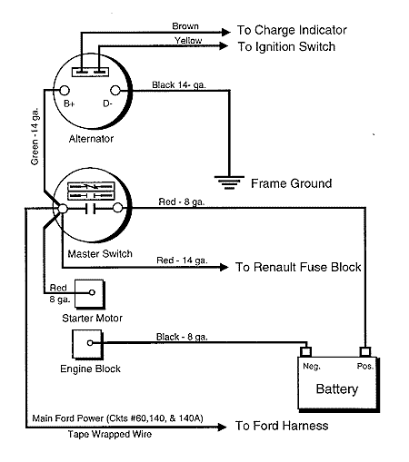 | ||||||
| Pro’s | Con’s | |||||
| - No
parts of the car are “hot” with the master switch off. - Zero current drain when the master switch is off. |
- Engine does not shut off when the master switch
is opened. - Fault codes are not retained after the master switch is opened. - EEC “learned” information is lost when the master switch is opened. | |||||
| Wiring Style #2 | ||||||
| Same as wiring style #1, but with a shorting resistor added to kill the alternator output when the master switch is opened -- thereby stopping the engine. | ||||||
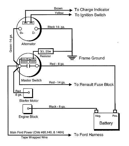 | ||||||
| Pro’s | Con’s | |||||
| - No
parts of the car are “hot” with the master switch off. - Zero current drain when the master switch is off. |
- Engine shut off when the master switch is opened
depends on the integrity of the shorting resistor and its wiring. - Fault codes are not retained after the master switch is opened. - EEC “learned” information is lost when the master switch is opened. | |||||
| Wiring Style #3 | ||||||
| Some significant changes here. This diagram appeared in the 2/17/94 update from Roush to SCCA Enterprises. In this wiring style, the power to the ignition switch is taken through the normally open auxiliary contacts of the master switch. Opening the master switch (putting it in the “normal” position), disconnects the battery from the alternator and the starter and --via the auxiliary contacts --- the alternator is disconnected from the ignition switch. The tape-wrapped EEC power wire remains connected to the battery at all times. This is the way my car is wired. | ||||||
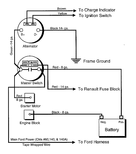 | ||||||
| Pro’s | Con’s | |||||
| - Fault
codes are retained after the master switch is opened. - EEC “learned” information is saved when the master switch is opened. |
- EEC is “hot” at all times the battery is
connected. - Clearing Fault codes requires disconnecting the battery. - EEC draws some (very small) current at all times | |||||
| Wiring Style #4 | ||||||
| This is the current “Green Book” wiring scheme. | ||||||
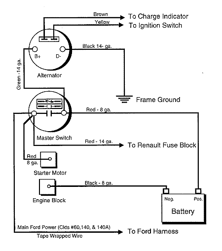 | ||||||
| Pro’s | Con’s | |||||
| - Zero current drain when the master switch is off. | - Alternator is “hot” at all times the battery is
connected. - Fault codes are not retained after the master switch is opened. - EEC “learned” information is lost when the master switch is opened. | |||||
| Rev. 3/14/98 | ||||||
| Feedback | ||||||
| I welcome your comments or ideas on this information. Feel free to drop me a line via “Comments for the Bro’s”. -Barry | ||||||
 LINK to Mumm Brothers Racing: Spec Racer Secrets |
||||||
END OF EXCERPTS Hope that helps. This is a 90 minute, "four beer" kind of job. Pretty rewarding if you're not real comfortable with this kind of mod, but want to get your hands dirty. Best wishes, S.A. McChesney aka "SteveRacer" 11/6/03 (C) 2003 S&S Diversified Feel free to Link ! | ||||||
